Ball balance
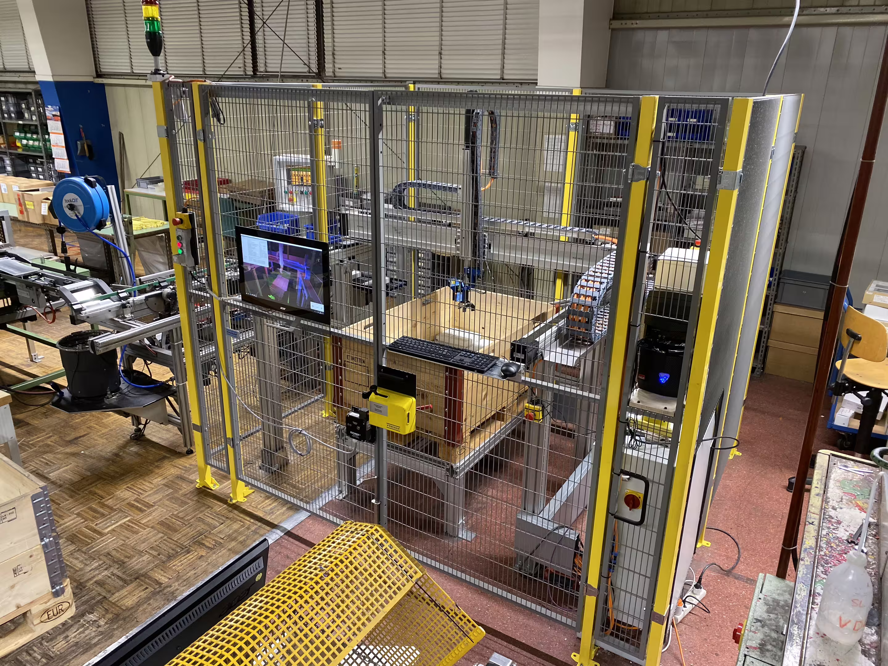
Experimental setup for control engineering lab

Teaching model for control engineering
The ball balance is a fascinating teaching model that clearly demonstrates the principles of control engineering. With a function block editor developed specifically for this purpose, students can independently design and optimize control loops. The aim is to control the tilt of the seesaw via a propeller drive so precisely that a metal ball is stably balanced in the center.
Ball balance as a teaching model for control engineering - THWS Schweinfurt - Engineer Glaser
🎱 The ball balance is a fascinating teaching model that clearly demonstrates the principles of control engineering. With a function block editor developed specifically for this purpose, students can independently design and optimize control loops. The aim is to control the tilt of the seesaw via a propeller drive so precisely that a metal ball is stably balanced in the center.
https://ingenieur-glaser.de/kugelwaage/ – Behind the scenes
#ControlEngineering #THWS #ElectricalEngineering #Prototyping #HardwareDevelopment #Microelectronics #Engineer #Matlab #Simulink #ATMEGA32 #Cplusplus #Cnc
💡️ Development & Manufacturing – Engineering firm Glaser
https://ingenieur-glaser.de/ – Electronics・Software・Hardware
🔔 Subscribe now! – Don't miss any development!
https://ingenieur-glaser.de/Instagram/ – Instagram
https://ingenieur-glaser.de/Facebook/ – Facebook
https://ingenieur-glaser.de/YouTube/ – YouTube
https://ingenieur-glaser.de/LinkedIn/ – LinkedIn
https://ingenieur-glaser.de/Twitter/ – Twitter
https://ingenieur-glaser.de/TikTok/ – TikTok
https://ingenieur-glaser.de/Xing/ – Xing
🥇 References – How visions became successes.
https://ingenieur-glaser.de/Projekte/ – References
📞 Contact – Has the spark been lit?
https://ingenieur-glaser.de/Kontakt/ – Contact
#ControlEngineering #THWS #ElectricalEngineering #Prototyping #HardwareDevelopment #Microelectronics #Engineer #Matlab #Simulink #ATMEGA32 #Cplusplus #Cnc #TeachingModel
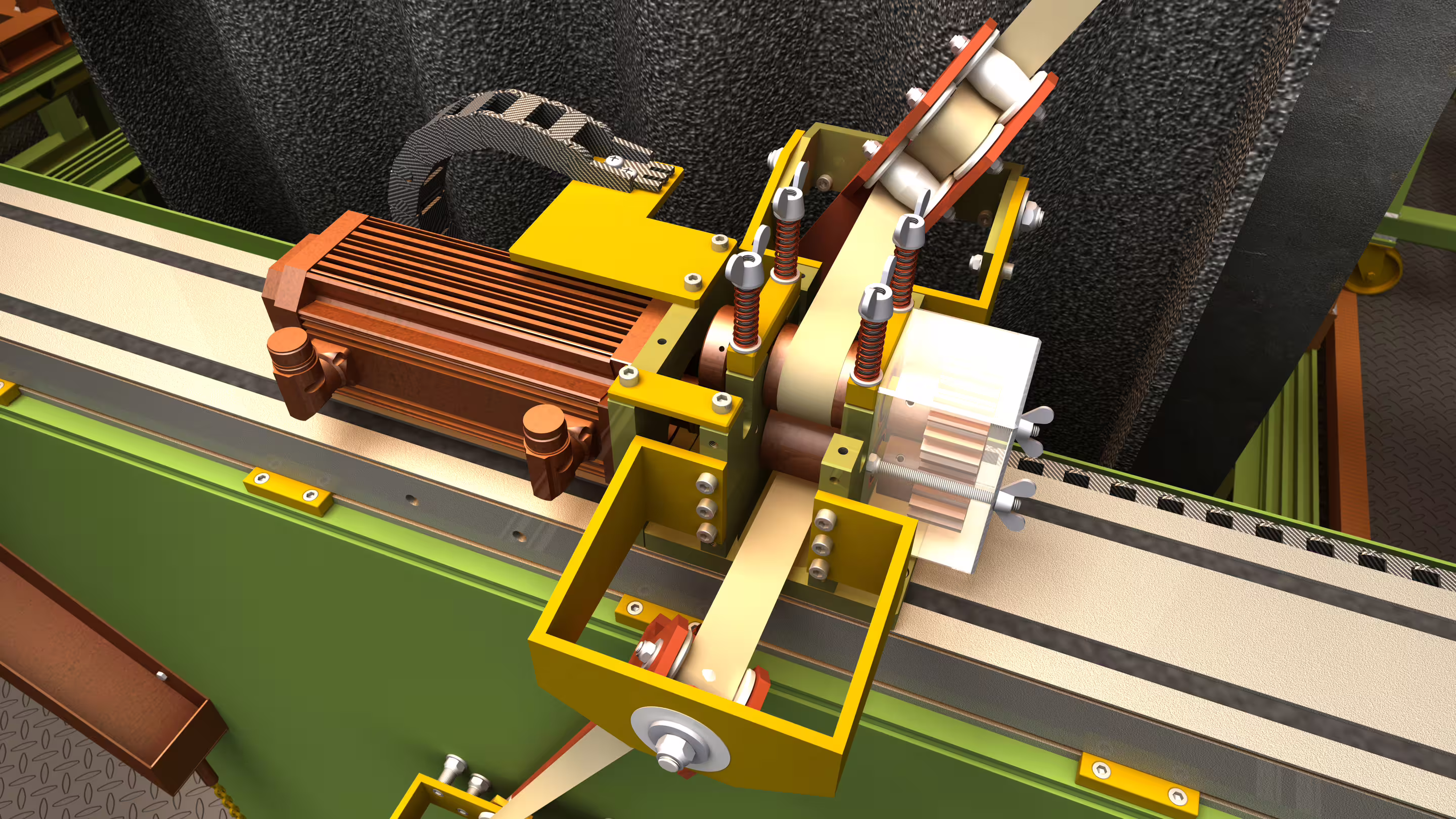
A challenging control process
At the center of the control process is a propeller drive connected to a pivot-mounted V-profile. A ball can roll freely on this. A servo motor changes the blade pitch to generate targeted thrust to the left or right and thus change the tilt of the seesaw.

The challenge is to develop a control loop that controls the highly dynamic and unstable system so that the rolling ball comes to rest in the middle of the V-profile. Even the smallest changes in tilt set the ball in motion. The ball's own weight acts as a disturbance as do varying propeller speeds and airflow turbulence. These factors significantly increase the complexity of stable control.

For control, the ball position and the tilt angle of the seesaw are available as measured variables. As the only actuator, a pitch-adjustable propeller must suffice to keep the ball in balance.
Unobtrusive sensor with impressive precision


Angle determination via an accelerometer


Thrust reversal thanks to pitch-adjustable rotor blades


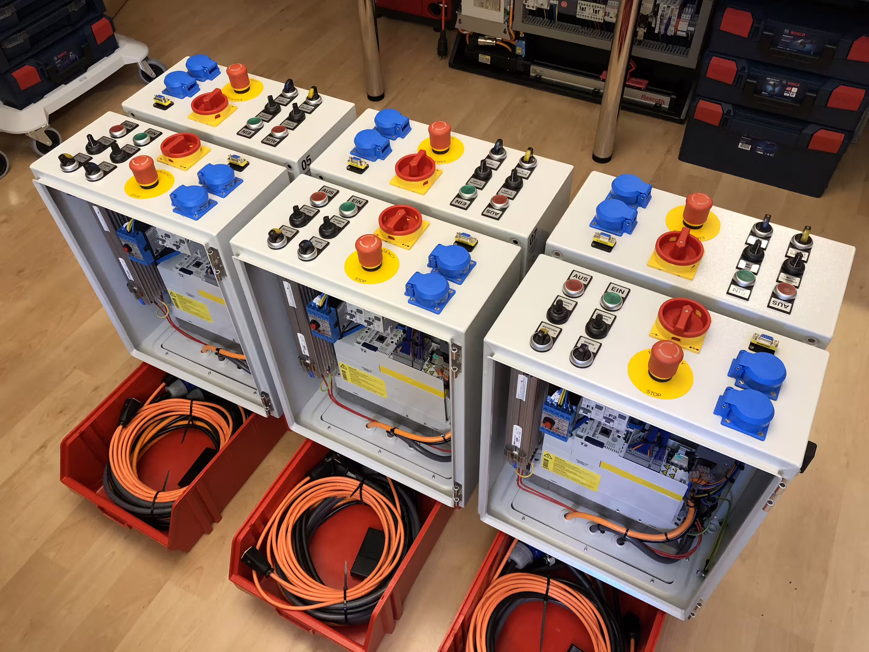
Signal and control interface with ATMEGA32 microcontroller

Control design with function block editor in VB.NET
For creating a controller, a function block editor specifically developed for this setup is available. The editor, written in VB.NET, includes all common control elements such as PIDT1 controllers and can be flexibly extended with user-defined function blocks. A special feature is the ability to edit the entire signal flow during runtime. Changes take effect immediately without requiring recompilation as is the case with e.g. MATLAB Simulink.

Controller design for a nonlinear, highly dynamic system
The ball and beam represents a complex, nonlinear control system. The developed control loop comprises a total of four cascades with five PIDT1 controllers, which act on the state variables of velocity and position of both the ball and the beam. Each cascade stage is finely tuned to reliably keep the ball centered despite the unstable conditions.


Manual control to illustrate the complexity
For a better understanding of the complexity, the experimental setup can optionally be controlled manually via a joystick. This quickly makes clear how demanding or nearly impossible it is to keep the ball balanced without an elaborate controller.


Manufacture of the wood, acrylic, and aluminum parts by CNC milling
All mechanical components were designed in AutoCAD and manufactured on a CNC milling machine. This enabled high precision fit and reliability in implementation.


Development Environments for Software Development
For programming the function block editor in VB.NET, Visual Studio was used, while for the microcontroller programming in C++ the ATMEL AVR Studio was used. Additionally, HTerm was used to monitor the serial communication between the microcontroller and the PC during development.


Fine motor soldering work on the BMA280 accelerometer


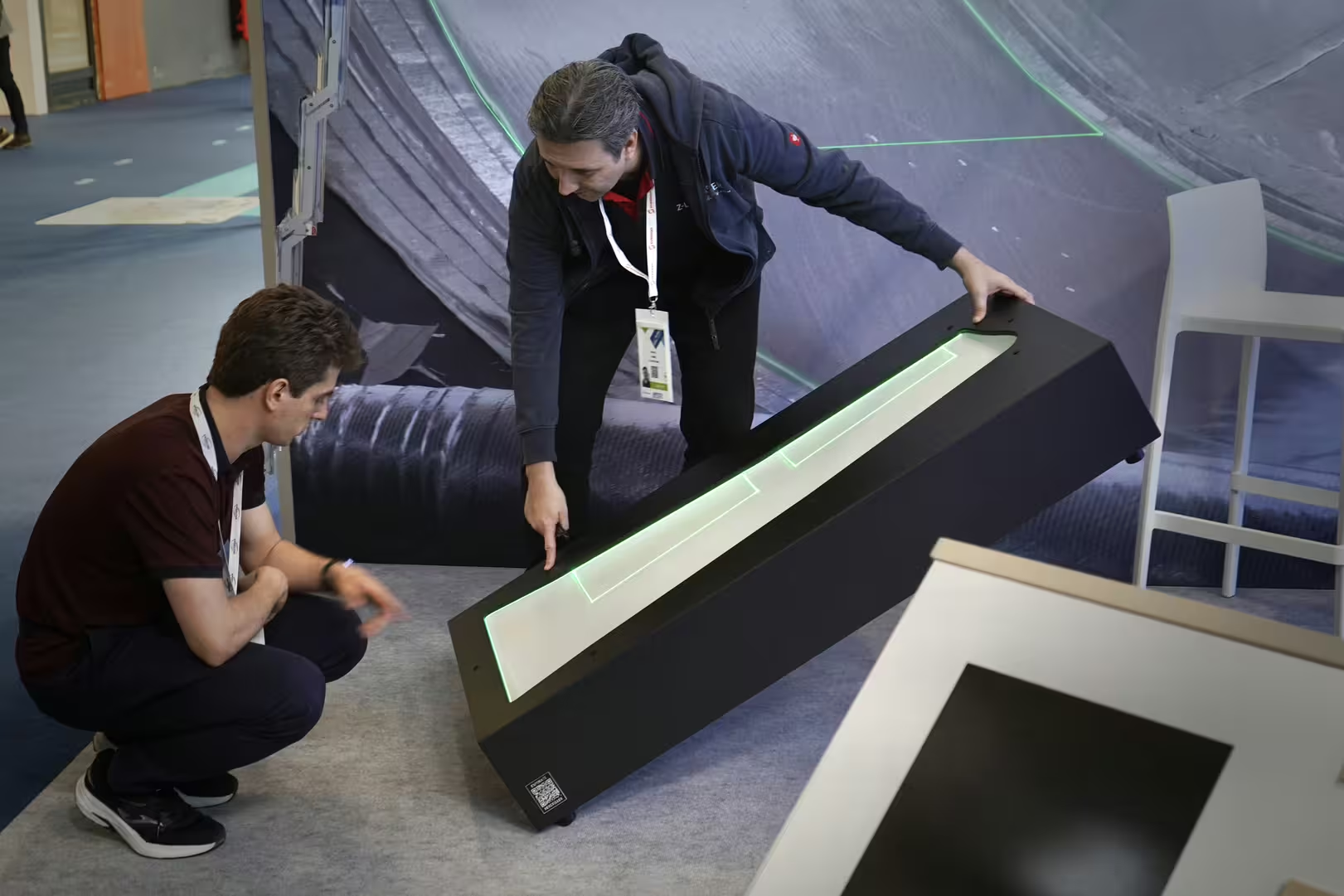
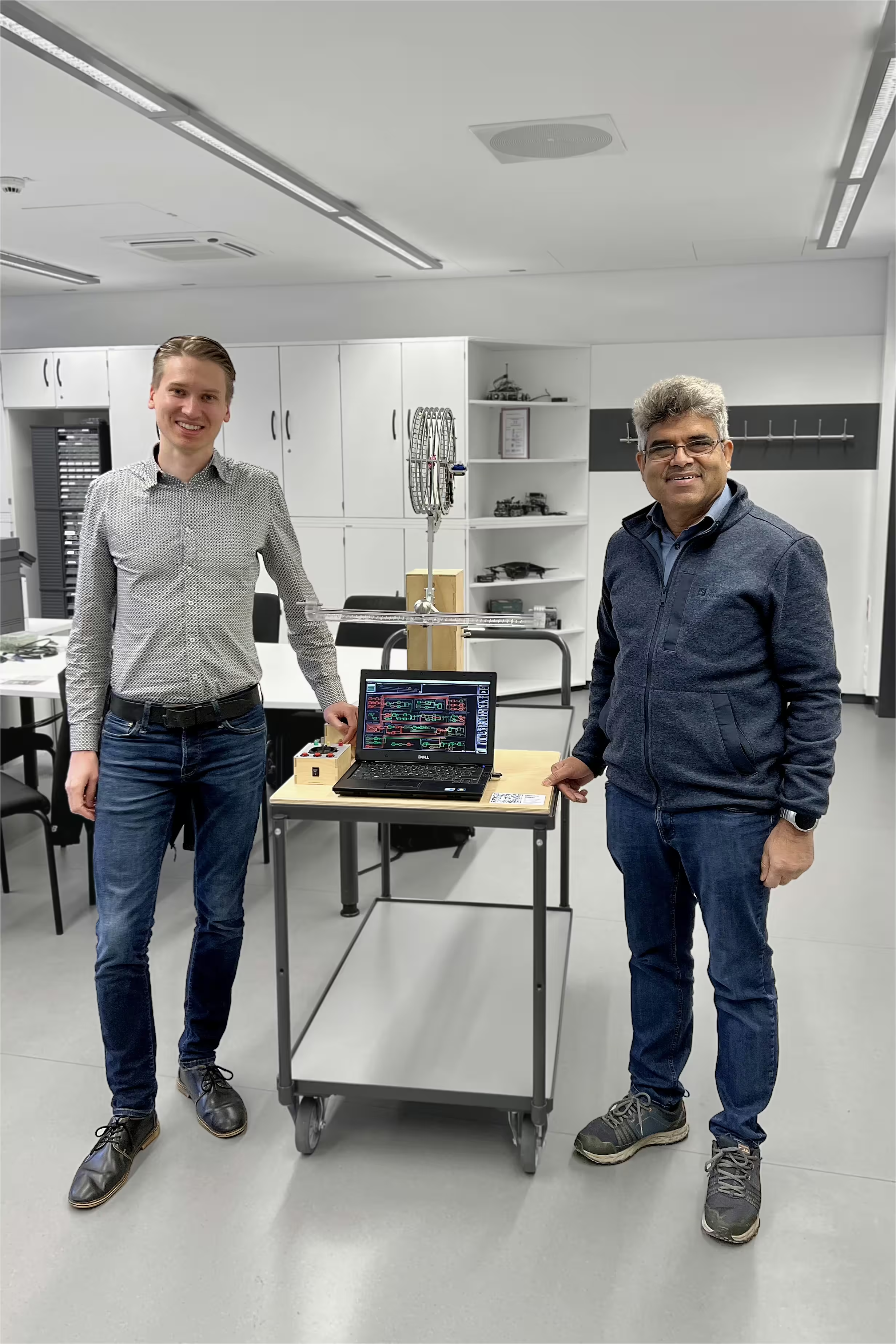
Handover of the experimental setup to THWS
The THWS (University of Applied Sciences Würzburg-Schweinfurt) has taken over the “Ball Scale” experimental setup for its control engineering laboratory. Prof. Dr. Abid Ali, who leads the lab, expressed his heartfelt thanks for the extraordinary commitment.
Pioneering spirit from student days strengthens control engineering lab
THWS thanks Johannes Glaser for the “ball scale,” a teaching model that enables students to learn control engineering in a hands-on way. ➔ Learn more now!

Ball Scale Challenge: Award for Outstanding Performance
The person who takes on the challenge and succeeds in developing a controller that stabilizes the ball precisely in the specified position will be awarded a certificate and a prize by Engineer Glaser. :)


THANK YOU!
Many thanks to Prof. Dr. Ali for the solid teaching of valuable control engineering tools during my studies. The practice-oriented and in-depth exercises complementing the lectures provided me with a solid foundation that still plays a central role in my engineering work today and has significantly contributed to my understanding of complex technical systems.